Why did the “Check Engine” light come on on a Honda?
The causes of the “Check Engine” lamp burning on various Honda models can be any malfunctions in electrical circuits or actuating units. In this case, the electronic system of the car receives a signal pulse with parameters different from the tolerance field. This data is written to the memory of the control unit as an error.
The most common reasons are:
- Violation of the composition of the mixture. Caused by poor fuel quality, failure of any fuel system sensor, clogged injection nozzles, or failure of the fuel supply pump from the tank.
- Mechanical problems in the engine. They are determined by sensors, such as valve timing offset.
- Breakage of sensors, rupture or oxidation of wiring harnesses between them.
Car Diagnostics
The latest Honda models have a large number of electronic components that can only be checked and adjusted using special diagnostic equipment. A typical example of such a task is the adaptation of the control unit of the V-belt variator, which should be carried out after changing the engine oil. To perform in-depth diagnostics, special adapters are used that connect to the diagnostic connector and laptop. The computer must have specialized Honda HDS (Honda Diagnostic System) software installed with a built-in and regularly updated Honda error database.
Primary diagnostics of the car can be carried out without special devices.
Using self-diagnosis, you can find out the presence of errors in the following systems:
- SRS – airbags;
- ABS – anti-lock braking system;
- Check Engine – system and sensors for ensuring engine operation;
- VSA – rectilinear motion preservation system;
- EPS – electric power steering.
During diagnostics, one or more lamps responsible for the operation of these systems will flash on the dashboard. Some errors are most conveniently detected using the self-diagnosis function, since they are not read by all types of scanners. An example of such errors are malfunctions of the airbag system (SRS). If there are no errors in the control unit, all control lamps on the combination will turn on and will not flash.
Do-it-yourself diagnostics on the most common Honda models is performed in the same way. The error codes of these machines are also standardized.
Namely, on vehicles such as:
- Partner;
- Torneo;
- Stepwagon RF1;
- SRV RD1;
- Orthia 4WD B20B;
- Civic (with a power plant or with a hybrid);
- Accord versions of CL9 and CC7 and many more.
How to conduct yourself?
To carry out the work, you only need a small piece of wire or a paper clip, which can close the pins of the connector contacts.
Let’s consider carrying out self-diagnostics using the example of such cars as the 2008 Honda Accord (CC7 or CF4 models), the 2001 Honda Stream:
- Prepare a clip for closing the contacts in the diagnostic connector.
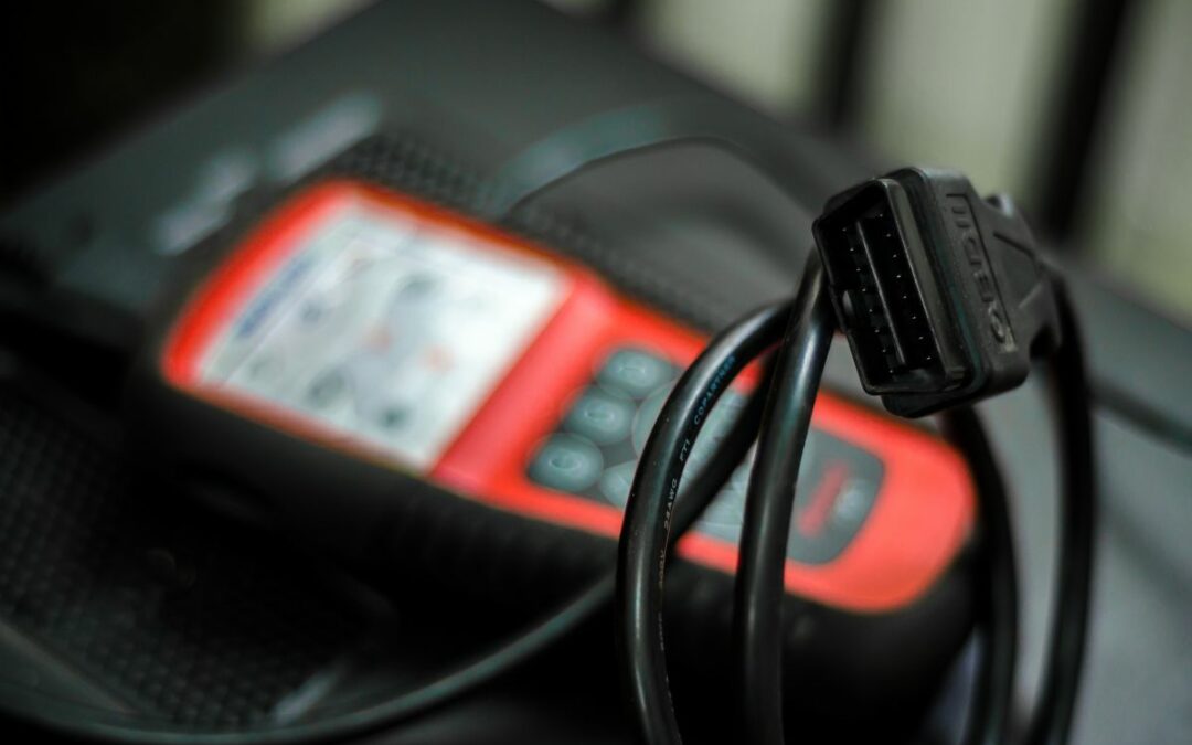
- Install it between the fourth and ninth pins of the connector located in the center console area (it can be on either side). This location is standard for placing the connector on almost all Honda models. Some cars are an exception: on the 1995–97 Accord, it is behind the ashtray on the console, and on the 2000 Legend, it is behind the trim around the automatic transmission selector. The 16-pin OBD-II-Honda connector itself is standard for all models after 1996 of release.
- Place the key in the lock, turn until the ignition system is switched on.
- During the diagnostic process, you should carefully look at the instrument cluster, remembering the number of flashes of the SRS, ABS, VSA, EPS and Check Engine warning lights. In this case, it must be borne in mind that the lamp counts tens by applying a long flashing pulse, and units – a short one. For example, a system error code 14 will be indicated by one long flash and four short flashes of the ABS lamp. During self-diagnosis, do not touch the brake pedal, as this will not allow you to read the ABS system errors.
- Decipher the read codes according to the tables.
On some machines, such as the 2002 Fit, 2004 Stream, or 2000 Prelude, sometimes it becomes necessary to find the right pins in the connector. This will require a low-power lamp with soldered wires.
To search for pins:
- Connect one wire of the control device to the body. It must be connected to an unpainted part of the body, a nut for attaching wires to the body, to parts of the engine or automatic transmission.
- Turn on the ignition and start with the second wire to alternately sort through the contacts in the connector.
- When you find the right pin, the “Check Engine” lamp located on the dashboard should turn on.
Devices for diagnostics and their cost
The most popular are adapters of the following types:
- Honda H.I.M. The most preferred option, although it requires a USB-COM adapter built on the FT232 chip. The Honda HDS program is supplied with the device. The average price of a kit (device, adapter, necessary cables and media with software) on the AliExpress website is about R1500, excluding shipping costs.
- ELM327. It has limited functionality because it is not compatible with Honda software. More affordable at a price that does not exceed R100 on AliExpress.
Deciphering codes
The codes read by the number of flashes must be deciphered to determine the faulty node. All Honda errors are divided into several main groups.
Diagnostic Trouble Codes
One of the most common errors on a Civic (left-hand drive and right-hand drive Ferio) or Fit GD1 is a problem with the engine components. The table below shows Honda error codes for 2007 and 2003 cars, respectively.
| Number | Malfunction |
| one | Error lambda probe and its wiring |
| 3 and 5 | Abnormal data on pressure in the inlet channel |
| 4 and 9 | Invalid data from the crankshaft sensor |
| 6 | Failure of the coolant temperature sensor |
| 7 | Errors in the operation of the throttle position sensor |
| eight | Failure of the sensor that determines the moments of top dead centers in the cylinders |
| ten | Intake Air Temperature Sensor Error |
| 12 | Failure of the EGR system |
| 13 | Faulty external pressure meter |
| fourteen | Idle air valve failure |
| fifteen | Malfunction of ignition coils |
| 16 | Failure of any of the fuel injectors |
| 17 | Speed Sensor Malfunction |
| twenty | Interruptions in the ignition system |
| 30–31 | Errors in the signals from the automatic transmission control unit |
| 41 and 63 | Faulty heating lambda probes |
| 43 | Incorrect pressure in the fuel supply system |
The most common mistakes when switching gears in automatic transmissions are considered using the example of Ferio and Stream models. Usually, all these errors are accompanied by sluggish acceleration of the car and the appearance of extraneous loud sounds when starting off.
| The code | Description |
| 5 and 6 | Incorrect functioning of contacts in the switching selector |
| 30 and 31 | Errors in the operation of the solenoids of the box |
| 32 | Breaks in the starting component solenoid wiring harness |
| 33 | Blocker failure |
| 34 | Failure of the system for determining the frequency of rotation of the input shaft |
| 35 | Similar, but only slave |
| 36 | Automatic transmission output shaft sensor |
| 42 | Incorrect operation of the shift control system |
| 43 | Start clutch defective |
ABS block errors
The anti-lock braking system in the brake drive is found on almost all Honda cars. The main causes of errors are damage to the rotation sensors and their wiring.
Table. Codes of malfunctions of system ABS.
| Fault code | Malfunction | Possible fault location |
| eleven | Open or short circuit in the front right wheel speed sensor circuit | Wheel speed sensor Wheel speed sensor rotor Wiring |
| 12 | Incorrect signal (signal distortion or sudden change in signal) of the front right wheel speed sensor | |
| 13 | Open or short circuit in the front left wheel speed sensor circuit | |
| fourteen | Incorrect signal (signal distortion or sudden change in signal) of the front left wheel speed sensor | |
| fifteen | Open or short circuit in the rear right wheel speed sensor circuit | |
| 16 | Incorrect signal (signal distortion or sudden change in signal) of the rear right wheel speed sensor | |
| 17 | Open or short in rear left wheel speed sensor circuit | |
| eighteen | Incorrect signal (signal distortion or sudden change in signal) of the rear left wheel speed sensor | |
| 21 | Malfunction of a rotor of the gauge of frequency of rotation of a forward right wheel | Wheel speed sensor rotor Wiring ABS control unit |
| 22 | Malfunction of a rotor of the gauge of frequency of rotation of a forward left wheel | |
| 23 | Malfunction of a rotor of the gauge of frequency of rotation of a back right wheel | |
| 24 | Malfunction of a rotor of the gauge of frequency of rotation of a back left wheel | |
| 31 | Pressure Modulator Solenoid Valve Malfunction | Solenoid valve ABS control unit Wiring |
| 32 | ||
| 33 | ||
| 34 | ||
| 35 | ||
| 36 | ||
| 37 | ||
| 38 | ||
| 41 | Front right is blocked during ABS operation | Wheel Speed Sensor Wheel Speed Sensor Rotor ABS Control Module Pressure Modulator Wiring |
| 42 | Front left is blocked during ABS operation | |
| 43 | Rear right is blocked during ABS operation | |
| 44 | Rear left is blocked during ABS operation |
Possible errors of the ABS block
On older machines, the valves of the hydraulic block and the block itself may fail. The following are additional errors of this system.
Table. ABS Fault Codes (Continued).
| Fault code | Malfunction | Possible fault location |
| 51 | ABS pump motor blocking | Pressure modulator ABS control unit Wiring |
| 52 | ABS pump motor does not turn on | ABS pump motor ABS control unit Wiring |
| 53 | ABS pump motor does not turn off (permanently running) | ABS pump motor ABS control unit |
| 54 | Malfunction of relay “Fail Safe” system ABS | Fail Safe relay ABS control unit Wiring |
| 61 | Low voltage | Power supply Wiring |
| 62 | High voltage | |
| 71 | The wheels installed on the car have different dimensions | Wheels of different dimensions are installed Tire pressures are not the same |
| 81 | Malfunction of the ABS control unit | ABS control unit |
ABS System Errors (Part 2)
Passive safety system
On many used Honda cars, for example, on the Orchia or Ferio, the indicator of defective airbags is often observed to light up. Causes can be wiring damage or sensor failure, as well as random errors in the system.
| The code | Decryption |
| 11-15 | Incorrect driver airbag control circuit parameters |
| 21-25 | Same for passenger airbag |
| 51-54 and 61-64 | Malfunction in the SRS control unit |
| 71-73 and 81-83 | Similarly |
| 91-92 | Similarly |
| 101 | Deployed front airbags |
EPS system
The most common errors in the electric power steering system are the failure of the electric motor or wiring.
The main error codes are shown in the table:
| The code | Designation |
| one | Power relay wiring damage |
| 2 | Malfunction in the control unit |
| 3-5 | Motor Power Problems |
| 11-14 | Various malfunctions of the rotation sensor and its power circuit |
| 21 | General amplifier failure, usually associated with a blown fuse and wiring |
VSA system error codes
This system does not apply to all vehicles. The main causes of errors are damage to the rotation sensors mounted on the wheels and their wiring. No less common is the failure of the lateral acceleration sensors and the VSA system unit itself. Listed below are some types of errors in this system.
Table. Codes of malfunctions of the VSA system.
| Fault code | Malfunction | Possible fault location |
| eleven | Open or short circuit in the front right wheel speed sensor circuit | Wheel speed sensor Wheel speed sensor rotor Wiring |
| 12 | Incorrect signal (signal distortion or sudden change in signal) of the front right wheel speed sensor | |
| 13 | Open or short circuit in the front left wheel speed sensor circuit | |
| fourteen | Incorrect signal (signal distortion or sudden change in signal) of the front left wheel speed sensor | |
| fifteen | Open or short circuit in the rear right wheel speed sensor circuit | |
| 16 | Incorrect signal (signal distortion or sudden change in signal) of the rear right wheel speed sensor | |
| 17 | Open or short in rear left wheel speed sensor circuit | |
| eighteen | Incorrect signal (signal distortion or sudden change in signal) of the rear left wheel speed sensor | |
| 21 | Malfunction of a rotor of the gauge of frequency of rotation of a forward right wheel | Wheel speed sensor rotor Wiring VSA control unit |
| 22 | Malfunction of a rotor of the gauge of frequency of rotation of a forward left wheel | |
| 23 | Malfunction of a rotor of the gauge of frequency of rotation of a back right wheel | |
| 24 | Malfunction of a rotor of the gauge of frequency of rotation of a back left wheel | |
| 25 | Malfunction in a chain of the gauge of a deviation from a course | Yaw sensor VSA control unit Wiring |
| 26 | Malfunction in a chain of the gauge of lateral accelerations | Lateral acceleration sensor VSA control unit Wiring |
VSA system errors, part 1
Table. VSA system trouble codes (continued).
| Fault code | Malfunction | Possible fault location | |
| 27 | Malfunction in a chain of the gauge of an angle of rotation of a steering wheel | Steering wheel angle sensor VSA system control unit Wiring |
|
| 31 | Pressure Modulator Solenoid Valve Malfunction | FR.IN FR.OUT FL.IN FL.OUT RR,IN RR.OUT RL.IN RL.OUT |
Solenoid valve VSA control unit Wiring |
| 32 | |||
| 33 | |||
| 34 | |||
| 35 | |||
| 36 | |||
| 37 | |||
| 38 | |||
| 41 | Front right is blocked during ABS operation | Wheel Speed Sensor Wheel Speed Sensor Rotor VSA Control Module Pressure Modulator Wiring |
|
| 42 | Front left is blocked during ABS operation | ||
| 43 | Rear right is blocked during ABS operation | ||
| 44 | Rear left is blocked during ABS operation | ||
| 45 | Pressure Modulator Solenoid Valve Malfunction | FRA FRD FLA FLD |
Solenoid valve VSA control unit Wiring |
| 46 | |||
| 47 | |||
| 48 | |||
| 51 | VSA pump motor blocking | Pressure modulator VSA system control unit Wiring |
|
| 52 | VSA pump motor does not turn on | VSA pump motor VSA control unit Wiring |
|
| 53 | VSA pump motor does not turn off (permanently running) | VSA pump motor VSA control unit |
|
| 54 | Fail Safe Relay Faulty VSA System | Fail Safe relay VSA system control unit Wiring |
|
VSA system errors, part 2
| 55 | Malfunction in a chain of the relay of system VSA | VSA system relay VSA system control unit Wiring |
| 61 | Low supply voltage (less than 10 V) | Power supply Wiring |
| 62 | High supply voltage (more than 16 V) | |
| 71 | The wheels installed on the car have different dimensions | Wheels of different dimensions are installed Tire pressures are not the same |
| 72 | System pressure too high | Pressure modulator VSA pump motor |
| 81 | Malfunction of the control unit of the VSA system | VSA system control unit |
| 83 | Communication error with the engine control unit | VSA system control unit Engine control unit Wiring |
| 84 | The VSA system operates continuously for 70 seconds or more
When the vehicle speed is more than 30 km/h, the VSA system operates continuously for 60 seconds or more (incorrect zeroing of the sensors) |
Yield sensor and lateral acceleration sensor zero set incorrectly Yield sensor Lateral acceleration sensor Steering angle sensor Wiring |
VSA system errors, part 3
Reset errors
After reading, the errors can be reset. This procedure allows you to find out if the error was random or it was caused by the failure of some electronic component in the vehicle. On Honda vehicles, various types of errors are reset in a certain way.
For example, to reset EPS system errors on a Honda Civic, follow these steps:
- Connect the pins of the diagnostic connector with a jumper wire, as in the self-diagnosis procedure.
- Insert the key into the ignition lock, turn the wheels all the way to the left and hold the steering in this position.
- Turn the key to the ignition on position and wait 4 seconds, after which the EPS warning lamp in the instrument cluster should go out.
- Over the next 4 seconds, you must return the steering wheel to the middle position. The EPS lamp should turn on again.
- After that, in the next 4 seconds, turn the wheels all the way to the left and hold in this position until the EPS lamp goes out.
- Return the steering to the middle position and after 4 seconds the EPS lamp should flash twice, which means that the memory of the control unit has been cleared of errors.
- Wait another 5 seconds for the system to learn the new center steering position. The end of this procedure will be indicated by three flashes of the EPS indicator.
- Switch off the ignition and remove the jumper from the connector pins.
- Turn on the ignition. If the EPS lamp continues to burn, then you should repeat the procedure again.
The errors of the ABS system that are in the memory can be reset on their own.
The sequence of actions on the Odyssey and CRV RD1 machines is as follows:
- Insert a jumper between pins 4 and 9 of the diagnostic connector.
- Depress the brake pedal with little effort and hold it in that position.
- Switch on the ignition and wait for the ABS indicator on the instrument cluster to turn off (approximately 2-3 seconds).
- After turning off the indicator, remove your foot from the brake pedal, after 4 seconds, the ABS signal will turn on again.
- Immediately after turning on the signal, immediately press the brake pedal and wait 4 seconds until the ABS lamp goes out.
- Release the pedal and after 4 seconds the ABS light should flash twice briefly. This is a clear memory signal.
- Turn off the ignition and remove the jumper from the pins.
After resetting these errors, an orange triangle with an exclamation mark may illuminate on the instrument cluster. This symbol indicates the presence of a VSA system error. In this situation, only the anti-lock braking system works. The procedure for resetting the VSA system is somewhat different. It will be considered on the example of the seventh generation Honda Accord.
To reset errors follow the steps:
- Close the fourth and ninth pins of the connector.
- Insert the key into the lock and lower the handbrake lever to the lowest position.
- Press the brake pedal with medium force and hold it until the end of the error reset procedure.
- Switch on the ignition and wait for the moment when the control signal of the ABS system on the combination goes out.
- Immediately after the lamp goes out, it is necessary to drown the button of the hand brake lever and lift it all the way up.
- Without releasing the button, quickly lower the lever back and up again.
- If the whole procedure is performed correctly, then the ABS lamp should give two flashes, signaling the removal of errors.
- Switch off the ignition and remove the jumper.
Resetting errors for right-hand drive or left-hand drive vehicles is carried out according to the same scheme. The only difference is the location of the mounting block.
Resetting SRS errors on a Honda XPV (common name – SHRV) is carried out in the following sequence:
- Remove the glove box housing in the region of the left (for left-hand drive cars) or right (for right-hand drive) knee of the driver, behind which the fuse box is located.
- Find a yellow connector with two pins in the block. It is usually located in the depth of the mounting element.
- Close the pins with a wire.
- Turn on the ignition.
- The SRS lamp will illuminate for 6 seconds and then turn off. After that, it is necessary to open the pins within 4 seconds.
- The SRS lamp will turn on again and the connector should be shorted in the next 4 seconds.
- The lamp will go out and within another 4 seconds the pins should be opened. The SRS indicator will flash twice.
- Turn off the ignition for 15-20 seconds.
Need Help with Error Codes or Honda Spares?
If you’re in need of help for deciphering error codes or in need of honda spares, please don’t hesitate to get in touch with us. We understand that it can be difficult to troubleshoot problems with your car, and we’re here to help. We deliver used honda parts throughout South Africa, so no matter where you are, we can get you the help you need. We know that when your car isn’t running like it should, it can be a major inconvenience. That’s why we’ll do everything we can to get you back on the road as soon as possible. Contact us today and let us help you get your car back in good condition. Thanks for choosing us!
Recent Comments